What Is an Ultrasonic Battery Welder?
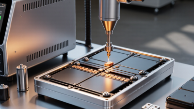
An Ultrasonic Battery Welder joins battery components through high-frequency mechanical vibrations, pressure, and carefully controlled energy. Unlike conventional arc welding, it normally creates a solid-state bond without melting the main materials. A metal tab may vibrate against a battery terminal for only a fraction of a second. The resulting joint can look small, but its electrical and mechanical performance matters greatly.
Dr. David A. Grewell, a recognized researcher in ultrasonic welding and polymer joining, has described the method this way: “Ultrasonic welding is a solid-state joining process in which high-frequency mechanical vibrations are used to create a weld.” This explanation captures the central principle. The tool presses the parts together while ultrasonic motion removes surface films and forms intimate contact. In battery manufacturing, that action can connect nickel, copper, aluminum, or coated tabs with limited heat exposure. That detail is important. Excessive heat can damage separators, coatings, or sensitive cell materials.
However, calling an Ultrasonic Battery Welder simple would be misleading. Real production involves fixture alignment, weld force, vibration amplitude, energy settings, and material thickness. A clean-looking weld can still contain weak bonding areas. Operators must inspect pull strength, electrical resistance, weld energy, and tool wear. Results may also change when surfaces become oxidized or contaminated. I initially viewed the process mainly as a fast joining technique. A closer examination shows a more demanding reality: repeatability depends on the entire system, not one machine setting. Reliable results require validated procedures, trained technicians, and documented quality checks.

What Is an Ultrasonic Battery Welder and How Does It Work?
What Is an Ultrasonic Battery Welder?
An ultrasonic battery welder joins battery tabs, foils, and terminals without relying on traditional solder. It uses high-frequency mechanical vibrations and controlled pressure. These vibrations move the metal surfaces against each other at the joint. Oxides and surface contamination are disrupted. The materials bond through solid-state welding, with limited heat generation. The nearby battery material stays cooler than it would during many thermal welding methods.
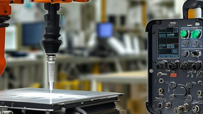
The process depends on three main controls: vibration amplitude, clamping force, and weld time. A horn presses the tab against the terminal. Then, ultrasonic energy travels through the horn into the contact area. Friction creates localized heat and plastic deformation. The metal surfaces connect without fully melting. This matters when joining thin copper or aluminum layers. However, those materials can reflect energy differently. Settings must match their thickness, hardness, and surface condition.
A reliable setup needs more than a clean-looking weld. Technicians commonly check electrical resistance, pull strength, cross-sections, and heat exposure. A neat weld can still be weak. That is the uncomfortable part. Tool wear, uneven pressure, or trapped contamination may remain invisible. Production teams should record each parameter and recalibrate equipment regularly. Small changes can affect thousands of joints. In practice, trial welds often require revision before the process becomes stable. Careful inspection remains essential.
What Is an Ultrasonic Battery Welder and How Does It Work?
An ultrasonic battery welder joins battery tabs and other thin metal parts by applying high-frequency mechanical vibrations under pressure. The representative waveform below uses a 20 kHz ultrasonic frequency, which is within the ultrasonic range commonly used for metal welding.
How it works: A transducer converts electrical energy into mechanical vibration. The vibrating horn moves the metal interfaces against each other, removing surface films and creating a solid-state bond without melting the entire workpiece.
Welding Process Steps: Clamping, Vibration, Bonding, and Inspection
What Is an Ultrasonic Battery Welder?
Welding Process Steps: Clamping, Vibration, Bonding, and Inspection
An ultrasonic battery welder joins conductive tabs, foils, or terminals through high-frequency mechanical vibration. It usually avoids added solder, reducing thermal exposure around sensitive cells. The result depends on pressure, vibration amplitude, energy, and material condition. Small changes matter.
Clamping holds the workpieces firmly between the sonotrode and anvil. Clean, flat contact surfaces are essential. Misalignment can create weak edges or visible marks. During vibration, the tool moves rapidly across the interface while controlled force maintains contact. Friction disrupts surface films and creates intimate metal contact. The machine then stops after a defined energy, time, or displacement target.
Bonding is not judged by appearance alone. Operators check weld width, peel strength, electrical resistance, and tab position. Cross-section analysis may reveal hidden voids or incomplete bonding. In a practical line, samples should be tested regularly, especially after tooling changes. Keep records of force, amplitude, weld time, and failure patterns.
The process is repeatable, not perfect. Dust, oxide layers, and uneven foil stacks can still cause variation. I would not approve a weld from visual inspection alone. A stable setup needs validated parameters, trained operators, and documented inspection criteria. Even then, occasional destructive testing remains valuable.
Material Compatibility and Typical 0.1–3 Second Weld Cycles
What Is an Ultrasonic Battery Welder?
Material Compatibility and Typical 0.1–3 Second Weld Cycles
An ultrasonic battery welder joins conductive parts through high-frequency mechanical vibration and controlled pressure. It usually creates a solid-state bond without solder, filler metal, or bulk melting. The tool tip presses battery tabs, foils, or busbar layers against an anvil. Vibration then disrupts surface films and forms intimate metal contact.
The weld itself may last about 0.1 to 3 seconds. It is fast. However, this number excludes loading, clamping, inspection, and part transfer. A copper tab may need more energy than a thin nickel-plated steel strip. Aluminum can also require careful control because its oxide layer resists bonding. Material thickness, hardness, surface condition, and layer count all affect the correct settings. Similar-looking materials may behave differently.
Practical qualification should measure electrical resistance, weld strength, visual consistency, and heat near the cell seal. Pull testing can reveal weak bonds that look acceptable. Cross-sections may expose partial bonding or excessive deformation. I would not treat a 0.1-second cycle as proof of productivity. A shorter weld can increase variation if the stack is uneven or the fixture is unstable. That is an important limitation. Operators should record amplitude, force, energy, and actual weld time for each material combination. Process windows need repeated trials, not one successful sample. Insufficient cleaning, misalignment, and worn tooling can quietly reduce reliability.
What Is an Ultrasonic Battery Welder? - Material Compatibility and Typical 0.1–3 Second Weld Cycles
| Material or Joint Type |
Typical Battery Application |
Compatibility |
Typical Weld Cycle |
Important Process Considerations |
| Aluminum foil or tab to aluminum tab |
Cell tabs, pouch-cell current collectors, busbar connections |
Highly suitable |
0.1–1.0 seconds |
Surface oxide, foil thickness, stack height, clamping force, and energy input strongly affect bond quality. |
| Copper foil or tab to copper tab |
High-current battery tabs, busbars, terminal joints |
Highly suitable |
0.2–1.5 seconds |
Copper requires adequate ultrasonic power because of its high thermal and electrical conductivity; excessive force can damage thin foils. |
| Aluminum to copper |
Mixed-metal tabs, busbars, and terminal transitions |
Suitable with process development |
0.3–2.0 seconds |
The different hardness, surface oxides, and electrical potentials require controlled tooling, amplitude, pressure, and weld energy. |
| Nickel-plated steel to nickel-plated steel |
Cylindrical-cell tabs, protection circuits, terminal components |
Suitable |
0.3–1.5 seconds |
The plated surface may weld readily, but plating thickness, steel hardness, and tab geometry influence the required energy. |
| Aluminum or copper to polymer separator |
Generally not used as a direct structural metal-to-separator weld |
Limited |
Usually not applicable |
Battery separators are normally protected from direct welding; ultrasonic energy can puncture, shrink, or thermally damage thin polymer films. |
| Thermoplastic housing or connector |
Battery housings, covers, cable connectors, and sensor assemblies |
Suitable for compatible thermoplastics |
0.2–1.0 seconds |
Common weldable plastics include ABS, PC, PA, PP, and some PBT grades; joint design and resin compatibility are essential. |
| Thick copper or aluminum busbar |
High-current modules and pack-level electrical interconnects |
Application-dependent |
1.0–3.0 seconds |
Greater cross-sectional area requires higher equipment capacity, optimized sonotrode geometry, and careful control of heat and vibration transfer. |
| Thermoset plastic, glass, or ceramic |
Specialized components only |
Generally unsuitable |
Not typically used |
These materials do not normally form the localized melt or solid-state interface required for a conventional ultrasonic weld and may crack under vibration. |
How the process works: An ultrasonic battery welder applies high-frequency mechanical vibration, clamping force, and controlled energy to create a solid-state metal bond or a localized thermoplastic weld. The commonly observed 0.1–3 second cycle includes vibration and bonding time; loading, part positioning, and inspection may add additional time.
Data note: Cycle times are representative engineering ranges rather than guaranteed specifications. Actual results depend on material grade, thickness, number of layers, joint area, surface condition, tooling, vibration amplitude, weld force, and required electrical resistance.
Quality Standards, Strength Testing, and Energy Use Below 2,000 W
What Is an Ultrasonic Battery Welder?
An ultrasonic battery welder joins metal tabs through high-frequency vibration and controlled pressure. It usually needs no solder, flux, or added filler. The process creates a solid-state bond with limited heating near the cell.
The power rating deserves careful reading. A 1,500 W system running for 0.2 seconds uses about 300 joules, or 0.083 watt-hours, before efficiency losses. Actual consumption depends on amplitude, weld time, clamping force, and standby demand. Below 2,000 W can still support reliable production. It does not guarantee low energy use.
The International Energy Agency reported nearly 14 million electric cars sold worldwide in 2023, increasing pressure for repeatable battery assembly. Small process errors now scale quickly.
Quality control should combine visual checks, pull testing, peel testing, and cross-sectional inspection. ASTM E8/E8M can support tensile-test planning, but engineers must adapt fixtures for thin battery tabs. IEC 62619 addresses industrial lithium battery safety; it does not replace weld validation. ISO 9001 practices help control calibration, traceability, and corrective actions.
A clean surface can hide weak bonding. That is the uncomfortable part. Test results may also change after aging, vibration, or thermal cycling. DOE battery manufacturing reports repeatedly emphasize process monitoring and defect reduction, yet many workshops still record only weld appearance. That approach needs reconsideration.